


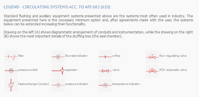
Legend
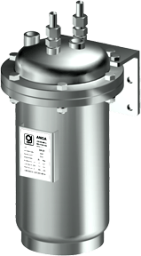
- 1. barrier gas panel
- 2. vent (if required)
- 3. barrier gas inlet (GBI)
- 4. barrier gas outlet (GBO), normally closed – used only for barrier pressure relief
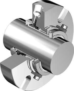
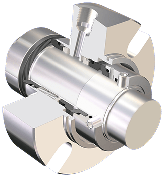
- 5. mechanical seal chamber
- 6. from barrier gas supply
- FIL. coalescing filter
- FIT. flow transmitter with local indicator
- PCV. pressure control valve
- PIT. pressure transmitter with local indicator
Barrier gas installation. Externally supplied barrier gas is used to positively prevent process fluid from leaking into the atmosphere. Pressure of the barrier gas is higher than the medium pressure on the technological process side of the inner seal. Venting of the gland box may be required prior to start-up and operation, to avoid the collection of gas in the pump.
Barrier gas installation operating according to Plan 74 comprises a power supply unit equipped with appropriate connectors and valves and control and measuring equipment. This installation is used with double gas-lubricated seals.
APPLICATION EXAMPLE

