


Legend
- 1. to vapor collection system
- 2. thin-walled tube
- 3. thick-walled tube
- 4. flush (F)
- 5. containment seal vent (CSV)
- 6. containment seal drain (CSD), closed
- 7. buffer gas inlet (GBI), plugged unless used with Plan 72 piping
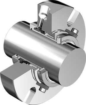
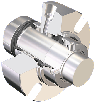
- 8. mechanical seal chamber
- PIT. pressure transmitter with local indicator
Installation of gas flushing for tandem double seal, which ensures draining of vapours to the discharge installation and/or control of leakage from the inner seal. Containment seal chamber drain for leakage which does not condense on seals. This Plan is used when the pumped medium does not condense at ambient temperatures. It is possible to monitor leak and/or vapours of volatile organic substances drained to the discharge installation.
Comments:
1. Light wall tubing shall be minimum 13mm (1/2″) in diameter and shall rise continuously from the CSV connection to the piping/ instrument set. 2. Piping shall be minimum 13 mm (1/2”) in diameter. Piping should be supported on an overhead construction or a stand in such a way that no stress is transferred onto the tubes connected to the seal gland box.
